Normal switched attenuators will give up to about 30dB attenuation, this is usually not enough, this is where the mixing/active attenuator comes in. These attenuators is based on a diode mixer, there is a huge selection of diodes available, the diode that is used in this unit is good for frequencies up to 2Ghz.
These are default with 4Mhz oscillators that would produce an offset image above and below the wanted frequency. By storing the target frequency and the target frequency-4Mhz (or target frequency+4Mhz) in two adjacent memory channels, would make the switch between attenuated and non attenuated signals nearly instantanious.
Transmitting into the diode mixer could damage the diode, we have an addon circuit that will protect the diode, but hte nett effect is that it could damage the PA in the Handheld Transceiver.
Double sided Through hole plated PCB, uses approx 4ma from a 8.4V Lithium pack, the design is for a 9V battery but will function from 10V down to about 6V.
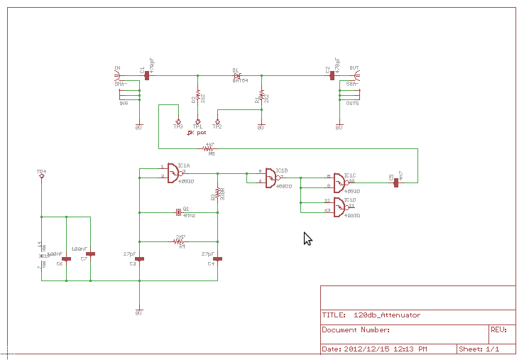
Download schematic here
Download pcb overlay here
Assembling your kit:
The only critical connections is the power, reverse powering the cmos device can damage it.
Take nate that there might be light solder marks on the main pcb, this is where we connected the test leads to make sure the attenuator is working correctly
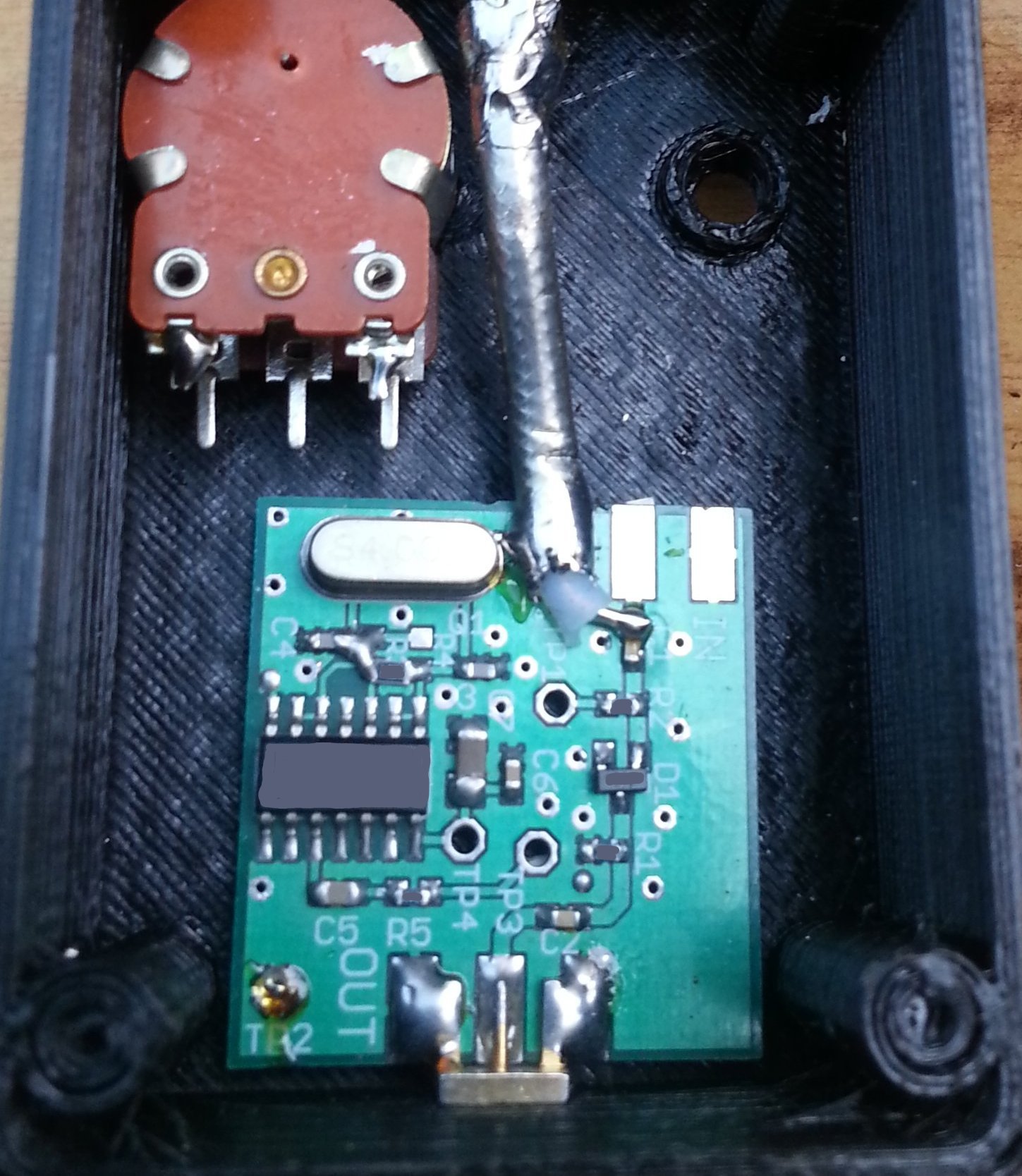
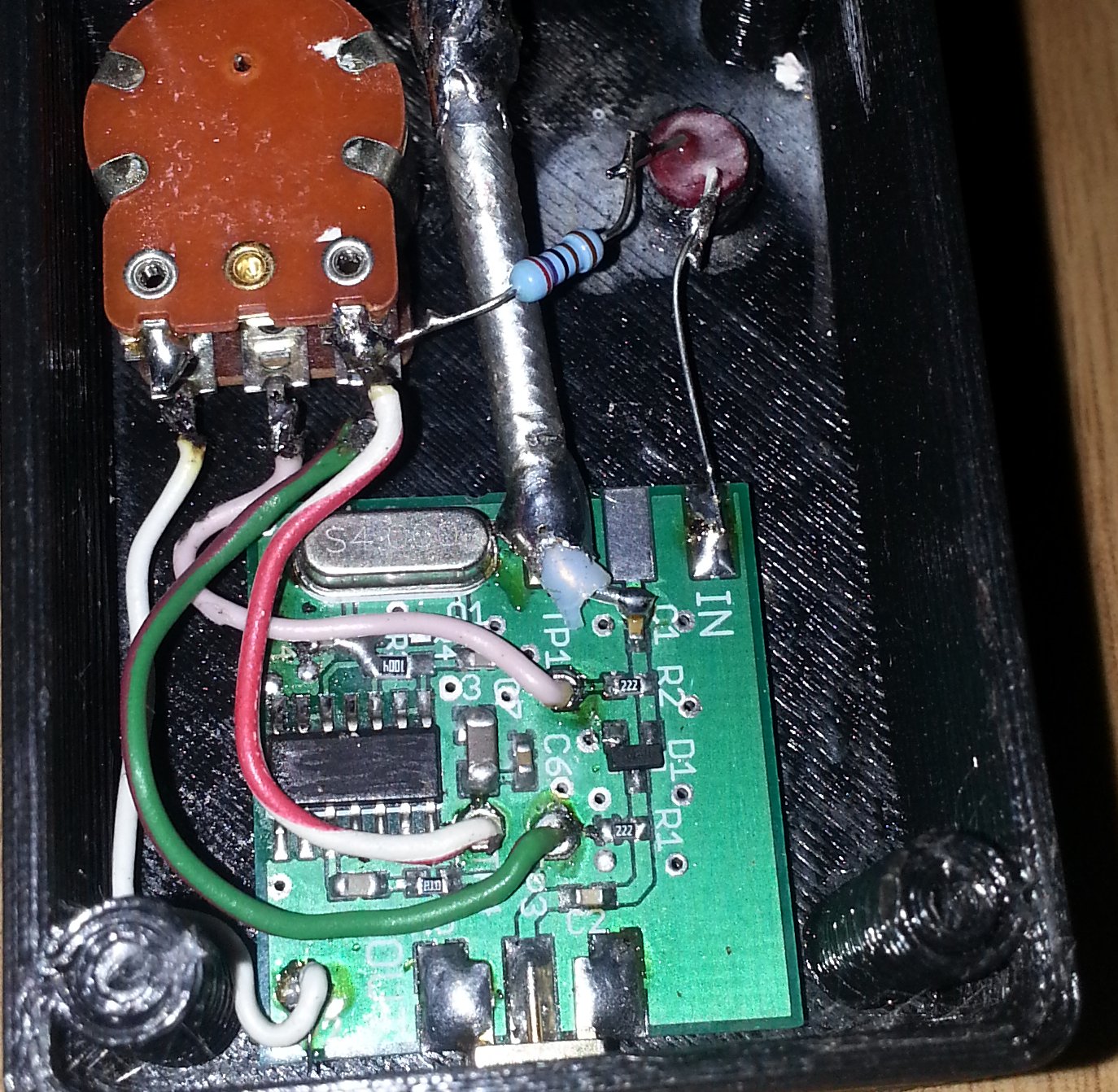
It is recommended that the unit be first installed in the box that you selected for it, see Picture below (This is one of our experimental units in a 3d printed box))
Click on Image for a larger photo:
Here the led is fitted with a series resistor of 2.7k ohm to the power switch, the ground connection to the pot is fitted to TP4, the wiper is fitted to TP1
Click on Image for a larger photo:
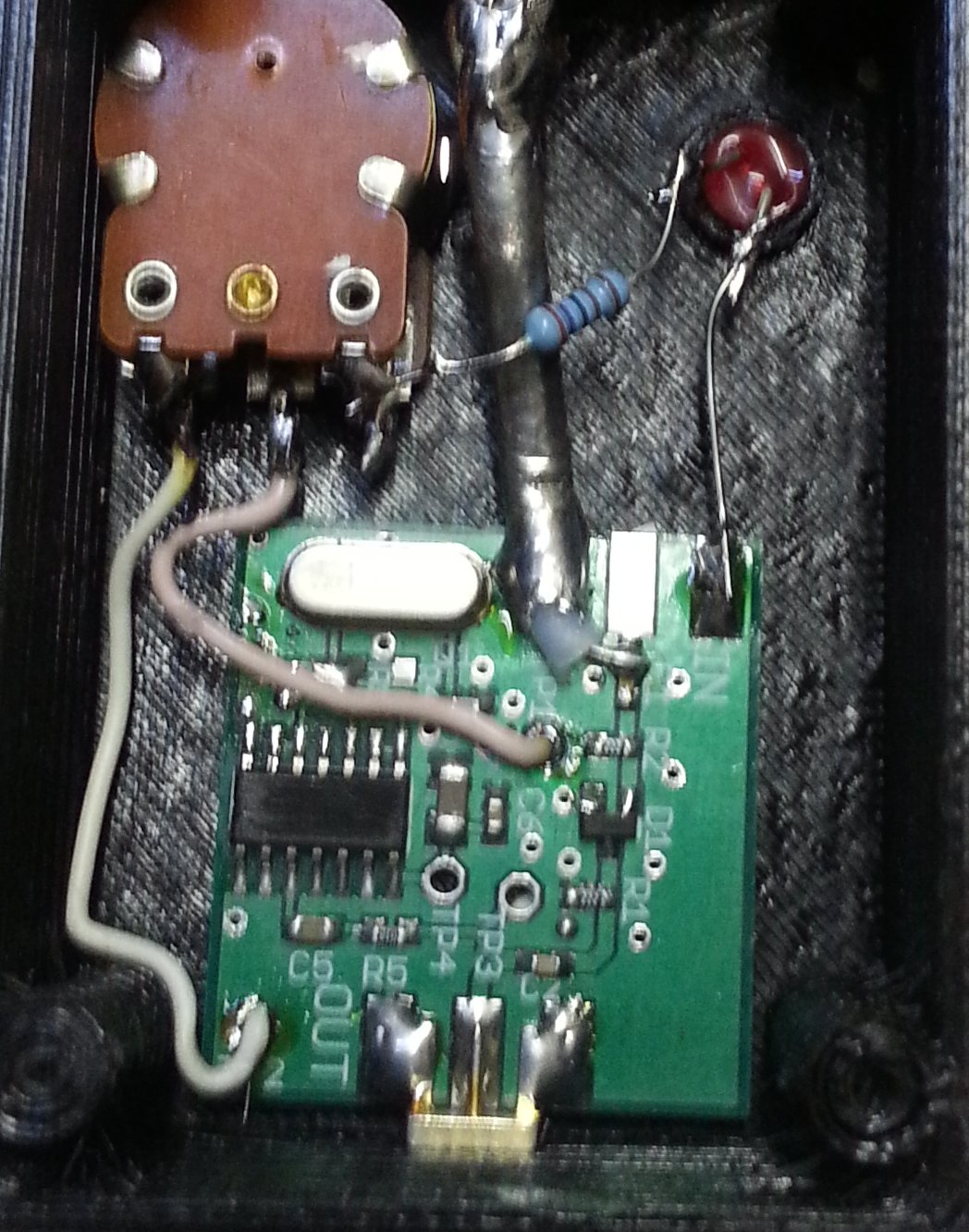
The remaining connection to the pot is connected to TP3
Click on Image for a larger photo:
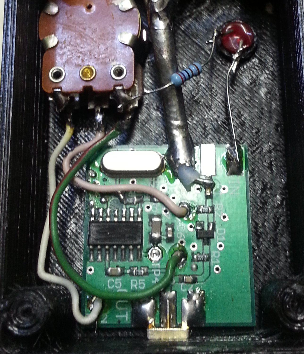
Now connect the switched power line to TP4
Click on Image for a larger photo:
a Note of caution, if you use a plastic box you will need something to shield the attenuator, we use copper tape that is soldered to the pcb
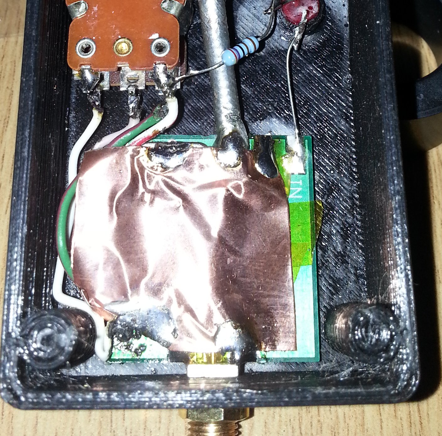
The Attenuator is now complete, connect the battery and power it up, the pot is wired to have minimum attenuation in the counter clockwise position (right at power off point), maximum attenuation would then be achieved in the complete clock wise position.